Semaphores

Multiprocessor or multitasking systems need a mechanism to coordinate inter-processor or inter-task communication.  In shared memory architectures the lowest level parts of this mechanism are usually called semaphores.  These can be used to request a resource such as I/O.  Typically this is a memory location that is tested to see if the resource is free and then set to lock out other actors.  Unfortunately an interrupt or separate processor might intervene between the test and set.  Some, but not all, processors have implemented test-and-set instructions that cannot be interrupted.  This protects against other tasks but the test-and-set instruction must also work with dual port memory and cache systems to hold off other processors.  The main problem is allowing multiple actors simultaneous write access to the same memory location.  Various solutions have been tried.  Some years ago, the UNOS operating system developed by Charles River Data Systems implemented eventcounts for low level signaling.  These 32 bit objects could only be incremented, preventing some of the problems with test-and-set semaphores.

For real-time industrial control a much more robust solution is necessary that satisfies a set of requirements.  1. Semaphores must be deterministic without the possibility of race conditions or ambiguity.  2. The solution must not require special processor features to allow portability.  3. Each semaphore is an entire smallest memory object that is written with a single memory cycle, usually an 8 bit byte or alternately 16 bit word for pure 16 bit memories.  4. Semaphores are provided in Query (Q) / Response (R) pairs. 5. Only one client actor may write a Q semaphore and only a single different server actor may write the associated R semaphore.  6. Each resource, be it a memory buffer, I/O, master state machine, or other is under the control of a single actor.  7. Enough distinct Q/R pairs are allocated to each client/server channel to unambiguously control all transactions.  8. At system configuration, and later as needed, semaphore pairs are assigned to client/server channels to establish the required communication channels.  9. Different processors or tasks may be servers for different resources.  10. Query and Response actions are performed in a single memory cycle.

As an example, when a channel is inactive, Qa and Ra are equal.  The specific value is irrelevant.  The client compares Qa and Ra.  If they are equal, the client may place a Query to request access to a resource such as a shared memory buffer by writing the logical complement of Ra into Qa.  When the resource becomes available the server copies Qa into Ra which signals the client that the buffer is available for reading and writing.  When the client finishes its data/control access it sends a query to Qb by writing the complement of Rb to it.  This signals the server that the client is finished with the buffer.  The server copies the Qb to the respective Rb to signal that it has regained control of the resource.  Note that this last is useful as otherwise the client might think the buffer is already requestable since Qa = Ra.  Bidirectional control transmissions may be passed from the server back to the client using additional Qc/Rc, Qn/Rn, … semaphores where Q is the server side.

Alternately, the above transaction could be

Client: [Qa = not Ra] ->

Server: [Qc = not Rc] ->

Client: Access …  -> [Rc = Qc] ->

Server: [Ra = Qa]

Note that in either case, the source of the query always sets the semaphore pair to a different value and the responder to the query always sets the semaphore pair to the same value.  In other words, an actor is not allowed to change its mind.  An abort request must be handled by a separate Q/R pair.  This is absolutely necessary for deterministic behavior.

This strategy works well in main memory for separate tasks and threads, shared memory for multiprocessors, and in hardware for handshaking to control communication buffers.

Please leave any comments using the post in my comments category.

Knurling on a Small Lathe

First a short note on lathe safety.  Modern industrial CNC lathes and machining centers have comprehensive safety systems including guards and light curtains.  Hobby and bench lathes are a completely different animal.  While a table saw or band saw will take off fingers, carelessness with a lathe will kill you.  Do not wear long sleeves or jewelry to include rings, bracelets, wristwatches, or necklaces.  Do not wear gloves.  Do not wear a tie, Bolo, or scarf.  Tie your hair back if it’s long.  Do not wrap crocus or emery cloth around your fingers to polish a moving part.  If you’ve had a drink, put off the lathe work until tomorrow.  Operating a lathe requires continuous attention, concentration, and clear judgement.  If you are interrupted or distracted, disengage the feed and step away from the lathe before turning to address the issue.

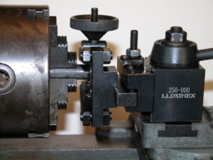
Knurling on a lathe is usually performed with a push type toothed roller tool as shown in figure 1.  The tool is pushed into the rotating part using the cross-slide.  This works fairly well on 12 – 14 inch and larger lathes.  Scaled down versions are traditionally supplied with smaller 6 and 7 inch lathes.  Figure 1 illustrates the tool supplied with the 6 inch Atlas lathe.  Using Atlas as an example, the 6 inch lathe looks just like the 12 inch, only scaled down.  The problem here is that a 6 inch lathe is not adequate to press regular knurls into harder materials like steel or brass.  The lantern tool holder and the cross-slide are simply not strong enough.  While it looks like it ought to work,  for proportional cross sections, a 12 inch lathe is 8 times stiffer and stronger in bending and 16 times stiffer and stronger in twisting than a 6 inch.  On YouTube, mrpete222 (tubalcain) has videos (#333-#336 ) about making a new 6 inch Atlas cross-slide to replace a broken one that obviously had too much force applied to the tool post.  I speak as someone who has broken a 6 inch Atlas/Craftsman lantern, although not while knurling.  The one in figure 1 is a slightly beefed up O1 replacement tempered to RC50.

Figure 1

Another problem with push type knurlers is that the stock has to be strong enough to resist bending under the knurling force and may need to be supported with a live center or steady rest.

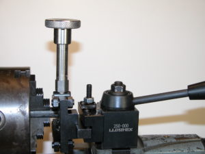
A solution to both problems is the pinch style knurler shown in figure 2.  In this style the part is trapped between an upper and lower roller.  Depending upon the model, the diameter is adjustable from 1 or 2 inches down to zero.  Since all the knurl force is due to the pinch between rollers there are no unbalanced forces against the work piece or the tool holder.  This allows knurls on unsupported long parts without difficulty.  The cross-slide simply centers the knurl wheels on the part and the carriage travel is used to make longer knurls.   As a result deep knurls on steel are easily produced even on the smallest lathes.  The remaining difficulty is that to start the knurl, the work piece needs to be turning while the clamping knob is tightened to the desired depth.   On short parts to be knurled near the chuck the small clearance between the spinning chuck and the hand adjust knob creates a major safety problem.  Figure 2 shows a stock tool.

Figure 2

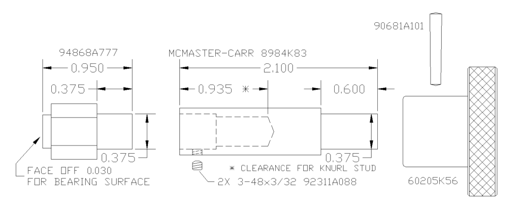
Here is the solution I came up with for my lathe.  A 3 inch extension of the clamp knob moves my hand far enough from the chuck for comfort.  I am not suggesting that you do this, just reporting on my solution to a perceived hazard.

Figure 3

I used a through tapped spacer from McMaster-Carr for the thread as I didn’t have a deep hole M6 tap and didn’t feel like counter boring all the way from the top.

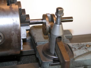
This is pretty mundane but now there’s one less thing for me to worry about.  By the way, the 0XA quick change tool holder as shown works well on the Atlas 6 inch.  Cutoffs are WAY better.  You will need to cut rabbets on the plate that comes with the tool holder as can be seen in figure 2.  A single piece of steel the thickness of the T-slot is not strong enough for a solid tool holder lock-down.  It flexes and doesn’t have enough thread engagement.

Please leave comments using the post in my comments category.
Staying alive on Venus

The most hostile place in the entire solar system that it is possible to land on is the surface of Venus.  The airless sun-baked surface of the Moon only gets to 260°F during daylight.  The surface of Mercury, closest to the Sun, peaks at 801°F.  But the surface of Venus is at 872°F both day and night with a corrosive atmospheric at a pressure of 1350 psi or 93 times the Earth’s.  The Russians, famed for rugged equipment, have landed probes on Venus at least 11 times.  The record for lander survival was set by Venera 13 on March 1, 1982, at 2 hours and 7 minutes.  Venus survival is so difficult that NASA is soliciting outside ideas with their Venus Rover Design Competition.  They are looking for ways to control and maneuver rovers without computers or electronics.  The main problem is that modern electronic devices cannot stand this kind of heat and die completely at 400°F or so.  It is completely infeasible to try to refrigerate the sensitive electronics and sensors because of the power requirements and the very high thermal gradient any refrigeration system would have to fight through. Not just the semiconductors and processors, but even current insulation and substrates, will not work at anywhere near these temperatures.  Nor will ordinary power sources.  Any lander will be accompanied by one or more orbiters that can receive information if it can be gathered.  Some creative ideas involve radar reflective panels that can be moved mechanically to change the lander albedo to signal data to an orbiter.  Others involve purely mechanical means for using extended probes to steer around holes and obstacles.

If you assume a pressure vessel, so the internal parts of the lander can be maintained at low or zero pressure to eliminate corrosion issues, the remaining problem is temperature.  While 872°F exceeds the working temperature of most engineering technology, this environment is actually within the reach of the amateur.  A typical self-cleaning kitchen oven runs at 900°F for a 4+ hour cycle.  Not as fancy as NASA’s Venus Surface Simulator but useful for testing magnets, bearings, insulators, and mechanisms.  One proposed solution to the power source problem is a windmill.  While the average wind speed on Venus is only 3 MPH, the air density is 93 times higher than on Earth, providing plenty of power for a windmill.  The main problems are bearings and power transfer.  There are hybrid ceramic and carbon sleeve bearings which are rated for these temperatures although not these pressures in this atmosphere.  Magnetic bearings eliminate friction and corrosion issues.  Unfortunately, the current top magnet material, Neodymium-Iron-Boron, loses its magnetism at such temperatures.  The next best, Samarium-Cobalt, has some high temperature versions that will only lose part of their strength.  These can be preconditioned at temperature and then used.  The older ALNICO 9 is able to work at Venus temperatures but starts out with about 1/3 the strength of Samarium-Cobalt.  It’s not clear which of an ALNICO or SmCo solution would be lighter and/or smaller.  Power could be transferred into the pressure vessel through a magnetic coupler consisting of a permanent magnet rotor surrounding an internal stator/generator separated by a nonmagnetic stainless steel cup in the wall of the pressure vessel. The overall idea is to figure out how to accomplish the science goals with technology that can operate at 872°F.

While NASA is looking into silicon carbide semiconductors, there are other possibilities.  One possibility is old tech: vacuum tubes.  In 1959 RCA invented the nuvistor, an advanced 0.4”x0.8” subminiature metal/ceramic vacuum tube.  While the kinds of glass subminiature tubes used in the AN/PRC-6 “walkie-talkie” radio might work at these temperatures, the nuvistor technology would be a better starting point.  One interesting feature was the RCA “dark cathode” that operated 630 degrees cooler than standard filaments.  The reduced heater operating temperature resulted in greatly increased tube life and reliability.  Starting at Venus temperatures would significantly reduce filament power.  More advanced materials might allow a Venus ambient temperature cathode without heater power.  The main problem is thermionic emission leakage from the grid, which limited the maximum temperature for the nuvistor.  In an advanced design, vacuum depositing a silicon dioxide film on the grid might produce an analog of an insulated gate, suppressing grid leakage.  There are metal-ceramic transmitter tubes like the 4CX150 that could be used as a starting point for developing high-temperature transmitter finals.  Circuit connections would need to be welded rather than soldered.  Most components would need to be rethought since traditional insulators will not work.  Capacitors could be air, glass, mica, or suitable ceramics.  Resistors could be metal film on ceramic or wire-wound on ceramic cores.  Inductors would be printed on ceramic laminated substrates or air-wound on ceramic spacers.  This is mostly existing radio technology.

One application would be small instrument packages that could be dropped in large numbers, consisting of a few simple sensors, a vacuum tube transmitter, and a solid electrolyte battery.  These are batteries already in use by the military.  They are extremely rugged and are completely solid and inactive at room temperature.  They are intended to run at temperatures in the Venus range where the electrolyte melts and becomes active.  Normally these batteries are actuated by pyrotechnic charges in artillery shells, rockets, or such but they could be part of a constellation of small Venus probes reporting temperature, seismic activity, or other data over wide areas for a limited time.  They would easily survive a multi-year space flight prior to insertion.  Multiple waves of probes could be used for longer data sets.

A long-term lander with a wind power source could support a wider range of sensors over a longer time frame.  With a method to generate high enough voltages and development of a high temperature photo cathode, it should be possible to use an image or line orthicon to transmit spectra.  Sapphire, ALON, or quartz windows would allow light sensing and slow-scan imaging.  Decades of television before the 1960’s demonstrated that this is well within the range of tube technology.  Mechanical scanning from an even earlier era is another possibility.  With magnetic bearings in a vacuum environment the scanner power consumption could be very low.  An idea brought up by various people is that you don’t need a computer or controller on the surface; you just need a receiver and transmitter in the lander with a control computer in the orbiter or orbiters.  Kind of like a really expensive drone.

Although NASA is looking into making processor chips out of silicon carbide, a non-trivial task, for over a decade computers were designed with vacuum tubes.  All logic functions, nand, nor, register, etc, can be handled by tubes, which in modern guise could be very small and very low powered compared to the best of the tube era, the nuvistor. While the original tube computers were monsters, they needed to run fast to solve major problems in a reasonable amount of time.  You don’t need much of a computer to miss a rock or transmit some data.  Specifically, a one-bit architecture like the PDP-8/S, WANG 500, or Motorola MC14500B with a little memory can compute anything with a minimum of physical hardware.  While it would be slow, it would minimize size and power consumption while providing adequate control for the lander.  A high temperature version of the Mercury computer program store could be a possibility here.

Please leave comments using the post in my comments category.