Martian Off-equator Space Elevator

A decades old science fiction theme (or dream) has been the space elevator. This is a (really strong) cable running from the equator through geosynchronous orbit and then on to a suitable stabilization mass. Vehicles running up and down the cable would provide an efficient, low cost, route to planetary orbit and beyond. The technical challenges are immense requiring materials far beyond current state of the art but perhaps possible.

Building such an elevator on Mars presents two additional problems, Phobos and Deimos, the Martian moons which are directly in the path of an equatorial space elevator, unlike Earth’s moon. The blocks below indicate the extremes of the moons’ orbits. One suggested scheme is to create an elevator that sways back and forth under power to miss each moon as it transits, every 11 hours for Phobos and every 131 hours for Deimos. This is recipe for disaster, constantly dodging near misses and hoping nothing goes wrong or wears out in the maneuvering system. Initially it seems reasonable to locate the ground end off the equator far enough that the cable is above the maximum latitudes of the moons with a large enough counterweight to stabilize the revolution. Unfortunately, while stable, there is no way to actually build it. The traditional equatorial based design is built out from geostationary orbit keeping the up and down masses equal until reaching the ground. This is impossible here. With the elevator plane of revolution over the 45th parallel for instance as there is no stable orbit to build from.

However, it may be possible to build it out from one of the poles.

The main idea is like swinging a weight on a rope around your head and then letting out more rope. As long as you spin the rope fast enough the weight does not fall to the ground. While this is a serious mega-engineering project, just making the cable is probably the hardest part. Start with a large, massive structure at the rotational pole. Think the great pyramid at Giza but much bigger. Vertically through the middle is a hollow shaft topped by an eccentric crank with a bearing that connects to the ground end of the cable. The hollow shaft is driven to spin the cable. A streamlined mass is attached to the end of the cable. At initial launch, the eccentric and short cable assembly are spinning fast enough to keep the mass off the ground. The space elevator is is built out from the center through the hollow of the shaft which would probably of kilometer order dimensions. As mass is added to lengthen the cable and increase the counterweight, angular momentum would slow the rotation but increased centrifugal force due to increasing radius would keep tension on the cable. At first the angular drive from the shaft would need to contend with the atmosphere, hence the streamlining, where the drive has greater leverage. This problem will be reduced once the bulk of the mass is outside the atmosphere. With care it should be possible to balance the slow down with the radius increase to bring the end of the cable to a stationary condition at design altitude. At this time the cable will be moving synchronously with the planet which will eliminate drag and the eccentric will be aligned with the cable and no longer turning. By moving the eccentric ahead or behind by turning the shaft slightly, small adjustments to the elevator’s revolution speed or longitude can be effected as the planet’s rotation pulls or eases on the cable.

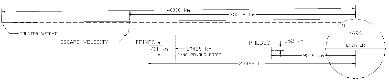
The figure illustrates the geometry for a 40,000km cable. This assumes negligible cable mass compared to the counter weight. Note the escape velocity locus. Any vehicle launched from the cable beyond this altitude will leave the Martian system without other effort. The plane of revolution is the 61st parallel. For this cable length the cable tension at the counter weight is 7.5 times the force of gravity. This makes the system fairly stiff against outside influences. For a 35,000km cable cable tension is 5.6 times gravity and the end is over the 53rd parallel. For a 30,000km cable the cable tension is 3.2 times gravity and the end is over the 43rd parallel. Shorter cables are cheaper but less stable in the presence of outside influences such as gravity from the moons and varying freight and vehicle transportation loadings. The closer the end gets to the equator, the less stable it is.

Please leave any comments in my comments post.

Staying alive on Venus

The most hostile place in the entire solar system that it is possible to land on is the surface of Venus.  The airless sun-baked surface of the Moon only gets to 260°F during daylight.  The surface of Mercury, closest to the Sun, peaks at 801°F.  But the surface of Venus is at 872°F both day and night with a corrosive atmospheric at a pressure of 1350 psi or 93 times the Earth’s.  The Russians, famed for rugged equipment, have landed probes on Venus at least 11 times.  The record for lander survival was set by Venera 13 on March 1, 1982, at 2 hours and 7 minutes.  Venus survival is so difficult that NASA is soliciting outside ideas with their Venus Rover Design Competition.  They are looking for ways to control and maneuver rovers without computers or electronics.  The main problem is that modern electronic devices cannot stand this kind of heat and die completely at 400°F or so.  It is completely infeasible to try to refrigerate the sensitive electronics and sensors because of the power requirements and the very high thermal gradient any refrigeration system would have to fight through. Not just the semiconductors and processors, but even current insulation and substrates, will not work at anywhere near these temperatures.  Nor will ordinary power sources.  Any lander will be accompanied by one or more orbiters that can receive information if it can be gathered.  Some creative ideas involve radar reflective panels that can be moved mechanically to change the lander albedo to signal data to an orbiter.  Others involve purely mechanical means for using extended probes to steer around holes and obstacles.

If you assume a pressure vessel, so the internal parts of the lander can be maintained at low or zero pressure to eliminate corrosion issues, the remaining problem is temperature.  While 872°F exceeds the working temperature of most engineering technology, this environment is actually within the reach of the amateur.  A typical self-cleaning kitchen oven runs at 900°F for a 4+ hour cycle.  Not as fancy as NASA’s Venus Surface Simulator but useful for testing magnets, bearings, insulators, and mechanisms.  One proposed solution to the power source problem is a windmill.  While the average wind speed on Venus is only 3 MPH, the air density is 93 times higher than on Earth, providing plenty of power for a windmill.  The main problems are bearings and power transfer.  There are hybrid ceramic and carbon sleeve bearings which are rated for these temperatures although not these pressures in this atmosphere.  Magnetic bearings eliminate friction and corrosion issues.  Unfortunately, the current top magnet material, Neodymium-Iron-Boron, loses its magnetism at such temperatures.  The next best, Samarium-Cobalt, has some high temperature versions that will only lose part of their strength.  These can be preconditioned at temperature and then used.  The older ALNICO 9 is able to work at Venus temperatures but starts out with about 1/3 the strength of Samarium-Cobalt.  It’s not clear which of an ALNICO or SmCo solution would be lighter and/or smaller.  Power could be transferred into the pressure vessel through a magnetic coupler consisting of a permanent magnet rotor surrounding an internal stator/generator separated by a nonmagnetic stainless steel cup in the wall of the pressure vessel. The overall idea is to figure out how to accomplish the science goals with technology that can operate at 872°F.

While NASA is looking into silicon carbide semiconductors, there are other possibilities.  One possibility is old tech: vacuum tubes.  In 1959 RCA invented the nuvistor, an advanced 0.4”x0.8” subminiature metal/ceramic vacuum tube.  While the kinds of glass subminiature tubes used in the AN/PRC-6 “walkie-talkie” radio might work at these temperatures, the nuvistor technology would be a better starting point.  One interesting feature was the RCA “dark cathode” that operated 630 degrees cooler than standard filaments.  The reduced heater operating temperature resulted in greatly increased tube life and reliability.  Starting at Venus temperatures would significantly reduce filament power.  More advanced materials might allow a Venus ambient temperature cathode without heater power.  The main problem is thermionic emission leakage from the grid, which limited the maximum temperature for the nuvistor.  In an advanced design, vacuum depositing a silicon dioxide film on the grid might produce an analog of an insulated gate, suppressing grid leakage.  There are metal-ceramic transmitter tubes like the 4CX150 that could be used as a starting point for developing high-temperature transmitter finals.  Circuit connections would need to be welded rather than soldered.  Most components would need to be rethought since traditional insulators will not work.  Capacitors could be air, glass, mica, or suitable ceramics.  Resistors could be metal film on ceramic or wire-wound on ceramic cores.  Inductors would be printed on ceramic laminated substrates or air-wound on ceramic spacers.  This is mostly existing radio technology.

One application would be small instrument packages that could be dropped in large numbers, consisting of a few simple sensors, a vacuum tube transmitter, and a solid electrolyte battery.  These are batteries already in use by the military.  They are extremely rugged and are completely solid and inactive at room temperature.  They are intended to run at temperatures in the Venus range where the electrolyte melts and becomes active.  Normally these batteries are actuated by pyrotechnic charges in artillery shells, rockets, or such but they could be part of a constellation of small Venus probes reporting temperature, seismic activity, or other data over wide areas for a limited time.  They would easily survive a multi-year space flight prior to insertion.  Multiple waves of probes could be used for longer data sets.

A long-term lander with a wind power source could support a wider range of sensors over a longer time frame.  With a method to generate high enough voltages and development of a high temperature photo cathode, it should be possible to use an image or line orthicon to transmit spectra.  Sapphire, ALON, or quartz windows would allow light sensing and slow-scan imaging.  Decades of television before the 1960’s demonstrated that this is well within the range of tube technology.  Mechanical scanning from an even earlier era is another possibility.  With magnetic bearings in a vacuum environment the scanner power consumption could be very low.  An idea brought up by various people is that you don’t need a computer or controller on the surface; you just need a receiver and transmitter in the lander with a control computer in the orbiter or orbiters.  Kind of like a really expensive drone.

Although NASA is looking into making processor chips out of silicon carbide, a non-trivial task, for over a decade computers were designed with vacuum tubes.  All logic functions, nand, nor, register, etc, can be handled by tubes, which in modern guise could be very small and very low powered compared to the best of the tube era, the nuvistor. While the original tube computers were monsters, they needed to run fast to solve major problems in a reasonable amount of time.  You don’t need much of a computer to miss a rock or transmit some data.  Specifically, a one-bit architecture like the PDP-8/S, WANG 500, or Motorola MC14500B with a little memory can compute anything with a minimum of physical hardware.  While it would be slow, it would minimize size and power consumption while providing adequate control for the lander.  A high temperature version of the Mercury computer program store could be a possibility here.

Please leave comments using the post in my comments category.

Eclipse 2017

My first total eclipse.  The moon relentlessly sweeping across the  dazzling surface and eating sunspots, heading towards a destiny that you know will come but can’t quite believe.  A hot August day cooling as the sun turns into a thin bright crescent. Baily’s beads and the diamond ring just before totality.  Suddenly the world turns strange as if you are in a Gothic movie.  The comforting brightness in the sky you’ve lived with all your life has become a photographic negative. The sky at midday is dark enough to see stars and planets.  Prominences  (9 o’clock and 11 o’clock upper left) and the spectacular corona burst into view.  There is sunset color on the horizon for 360 degrees around you.  Cheers and tears, everyone seems to have an emotional response.  Words cannot do it justice.  Pictures cannot do it justice.  There is no way to convey what the experience is like, standing out under the open sky, with that incredible event happening overhead.  Don’t miss the next one.

Microgravity Volume Gauge

Traditional methods of gauging fluid levels in a tank include inserting a measuring stick as is done at gasoline stations around the world, using a float mechanism, measuring the distance from the tank top to the fluid surface via ultrasonics or something similar, or sensing the pressure at the bottom of the tank due to the weight of the fluid.  These methods all have two problems.  The exact shape of the tank must be known for accurate readings.  And, since they only work in a stationary tank in a gravity field, they are completely unsuited for microgravity.  Here is an alternative in the irrelevant tech spirit.

Microgravity Induced Bone Loss

The two critical problems faced by manned deep space exploration are radiation (discussed in a later post) and microgravity induced bone loss.  NASA has been studying bone loss in astronauts for 50 years and has learned enough about the biological mechanism to develop the successful ARED exercise device and nutrition protocols for the ISS.  These work well for motivated, fit astronauts, but compliance might be problematic for the larger and varied crew of a very long duration deep space mission.  The traditional hard science fiction solution is to use spin to generate centrifugal gravity.  One question is how much spin?  When (hopefully) we have Lunar, 1/6 G, and Martian, 3/8 G, permanent bases we will be able to do comparative bone loss studies.  A rat centrifuge on the ISS could produce additional data.  It is inconvenient to spin an entire spacecraft because of issues with navigation, antenna orientation, maneuvering, and frame stress.  Spinning part of a craft creates problems with seal integrity between the sections.  The internal wheel of the 2001: A Space Odyssey spacecraft was a rather elegant solution to these problems but still represents an unlikely level of technology for the foreseeable future.  It is likely any long duration manned space mission in the next 50 years will need to deal with the problem of microgravity.

The research that resulted in the ARED and also related rat research have shown that it is the lack of resistance to movement or lack of force supporting body weight stressing the long skeletal bones, rather than lack of the internal force of gravity on the bone matrix, that causes bone density loss.

Fully aquatic mammals such as whales, dolphins, and manatees spend their entire lives in a neutral buoyancy environment, effectively weightless.  While the deep dives of whales and the hunting acrobatics of dolphins may or may not give their skeletons astronaut levels of stress, manatees are the original couch potatoes.  In any case, all are fully adapted to their environment.  While none of these animals are remotely suitable for research, it is almost certain that we have DNA samples for all of them which could be sequenced.  We also have DNA for their land based relatives – hippopotami, elephants, and hyraxes – for comparison.

As NASA’s and others’ research into microgravity induced bone loss proceeds, the signaling and metabolic pathways involved along with their associated proteins will be identified.  It would be useful to compare these proteins to the aquatic equivalents to try to identify any adaptive changes.  This might suggest new paths for the pharmaceutical research already underway in rat studies.

Looking homeward

For 13 years the Cassini spacecraft has been orbiting Saturn and its moons, sending back thousands of spectacular pictures.  Now nearing the end of its mission, it will be exploring the ring system and ultimately entering Saturn’s atmosphere on September 15th, 2017.  Once in a while when the geometry is suitable, Cassini pauses to take a picture of the Earth while moving between science targets.  These homeward looks from 900 million miles away evoke a haunting loneliness.