Jointer knife adjustment jig

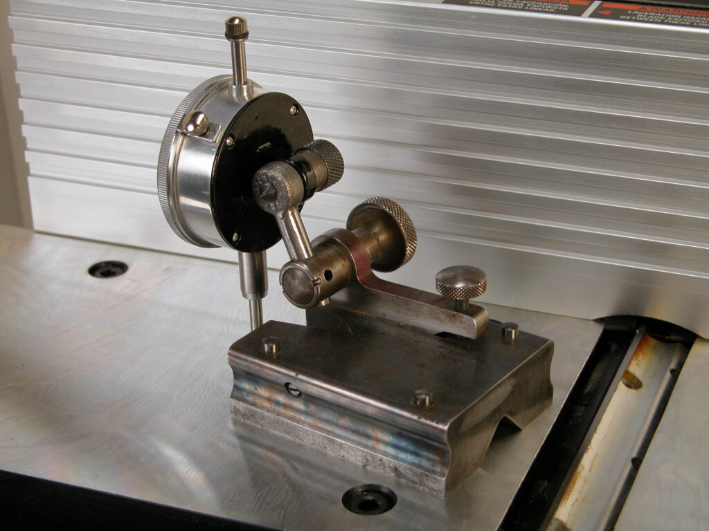
The jointer is the fundamental woodworking power tool for creating flat, square lumber without cup, bow, or twist.  It is the first step in preparing wood for woodworking.  The most critical jointer adjustment is ensuring that the cutter knives are precisely coplanar with the outfeed table.  Otherwise you will not be able to successfully produce lumber that is flat and free of scarfs.  The typical user guide instructions are to place a straightedge on the outfeed table overhanging the knives and then adjust the knives and/or the outfeed table until the knife edge just touches the straightedge across the width of the table, which is fairly imprecise and gets more difficult as your eyes age.  The illustrated jig allows you to easily adjust the alignment to within 0.001″ or so.

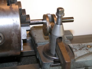
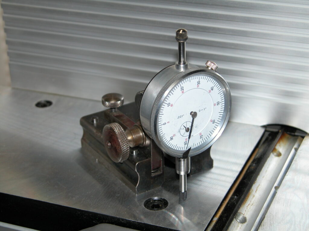
This one consists of an inexpensive ($15 at Amazon) dial indicator mounted on an old surface gauge base.  Note the flat tip on the indicator plunger.  Dial indicator plungers come with ball ends which are not suitable for measuring a knife edge.  These ends are replaceable and all use 4-48 threads.  The flat one above is www.mcmaster.com part number 20625A661.  The mounting strut is a rod end blank, 6065K171.  You can save yourself some machining by cutting down a 6066K34.  It is important to get the axis of the plunger square to the surface.  This makes the measurement insensitive to small changes in position.

With the end of the plunger on the same surface as the base, turn the dial bezel until the indicator index (the small black triangle at the bottom of the dial in the top image) matches the dial reading.  The plunger tip is hardened…if you drop it on your cutter edge you may damage the cutter.  Pull up on the top of the plunger and slide plunger over the knife edge.  Then gently lower the plunger.

Follow your jointer cutter/outfeed adjustment instructions to bring the dial reading into alignment with the index flag.  Repeat across the outfeed table.

The base doesn’t need to be this fancy, just stable.  I happened to have this on hand.  A piece of angle iron with three screw adjustable support points to square it up would do as well.

Please leave any comments using the post in my comments category.

Ortgies

The Ortgies is a 1920-1927 production German pocket pistol that was very popular at the time and was imported in large quantities into the US.  It is externally similar to the Colt pocket pistol but completely different internally.  It is comfortable and pleasant to shoot.

In many ways it is an elegant design.  It has no screws.  It is nicely finished with no corners to catch on a pocket.  As a 100 year old striker fired pistol it should never be carried with a round in the chamber.  Here is a very good article about these pistols, and another here.

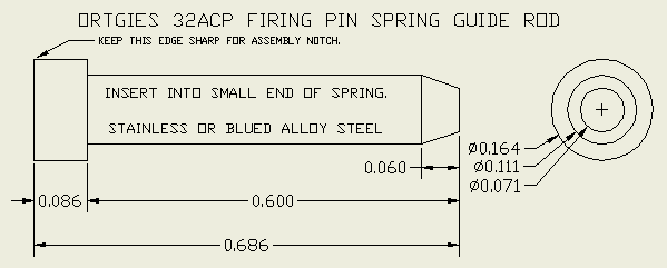
The main quirk of these pistols concerns the firing pin spring guide rod.  Firstly, when you field strip one of these the guide rod launches itself (with or without the spring) out the back of the pistol.  Field stripping instructions usually include an admonition to cover the back of the slide with a finger, disassemble in a plastic bag, or just to “take care” to not lose the guide rod.  Secondly, assembly is difficult unless you know the “trick”.  There is an assembly notch on the underside of the slide above the guide rod channel.  To assemble, compress the guide rod and spring and push it up into the notch.  Then you can replace the slide normally.  This is best practiced a few times without the firing pin spring and guide rod as bobbling the slide installation will also launch the guide rod out the back.  There are at least two different Ortgies guide rods.  One is 0.842″ long which is too long to fit in the assembly notch of some pistols.  Here is one that works in a fifth style 32ACP pistol which is the majority of production.

Note that it is important to insert this into the small end of the spring and insert the large end of the spring into the firing pin housing.  Otherwise the pistol will jam.

One other note, do not attempt to remove the grip panels without comprehensive disassembly instructions.  There is a latch inside the magazine well which must be pressed in to release the back edge of the grip panels. The front of the panels are hooked into the frame.  Great care must be taken as the wood engagement surfaces are very small and comparatively fragile.  In general, the grips should not be routinely removed as this is unnecessary for cleaning and only necessary for a detail strip.

Please leave any comments using the post in my comments category.

Astraea

I came across a bit of poetry by Emerson that is apropos to the times we find ourselves in:

Each the herald is who wrote

His rank, and quartered his own coat.

There is no king nor sovereign state

That can fix a hero’s rate;

Each to all is venerable,

Cap-a-pie invulnerable,

Until he write, where all eyes rest,

Slave or master on his breast.

Fast Settling PLL Multiplier

Phase Lock Loops have long been used for clock recovery, fixed frequency multiplication, reducing clock jitter, frequency synthesis, FM modulation / demodulation, and other tasks.  The basic PLL consists of a Phase/Frequency Detector, loop filter, and Voltage Controlled Oscillator whose output is fed back to the detector through an optional digital frequency divider.  When the loop locks to the input frequency, the output frequency is equal to the input frequency times the divider ratio.

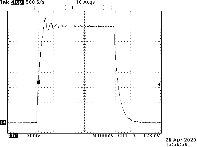
Direct Digital Synthesis circuits have supplanted PLLs in many synthesizer roles but the PLL has the advantages of cost, simplicity, and the ability to maintain constant phase lock to the source.  RCA application note ICAN-6101 describes the use of a CD4046 Phase-Locked-Loop IC as the heart of a 3 digit 1KHz to 1MHz synthesizer.  Note that for synthesizer applications it is necessary to use the Frequency detector PC2 rather than the simple Phase detector, PC1.  The biggest issue with this circuit is that the loop damping factor varies with the square root of the loop gain which is the product of the PFD and VCO gains divided by the division ratio.  The PFD gain is in volts per Hz and the VCO gain is in Hz per volt so the loop gain is dimensionless.  At high division ratios, i.e. high frequencies, the loop is under damped and is over damped at low frequencies.  This is a trace of a standard PLL synthesizer  VCO control input switching between 3KHz and 1.024MHz.

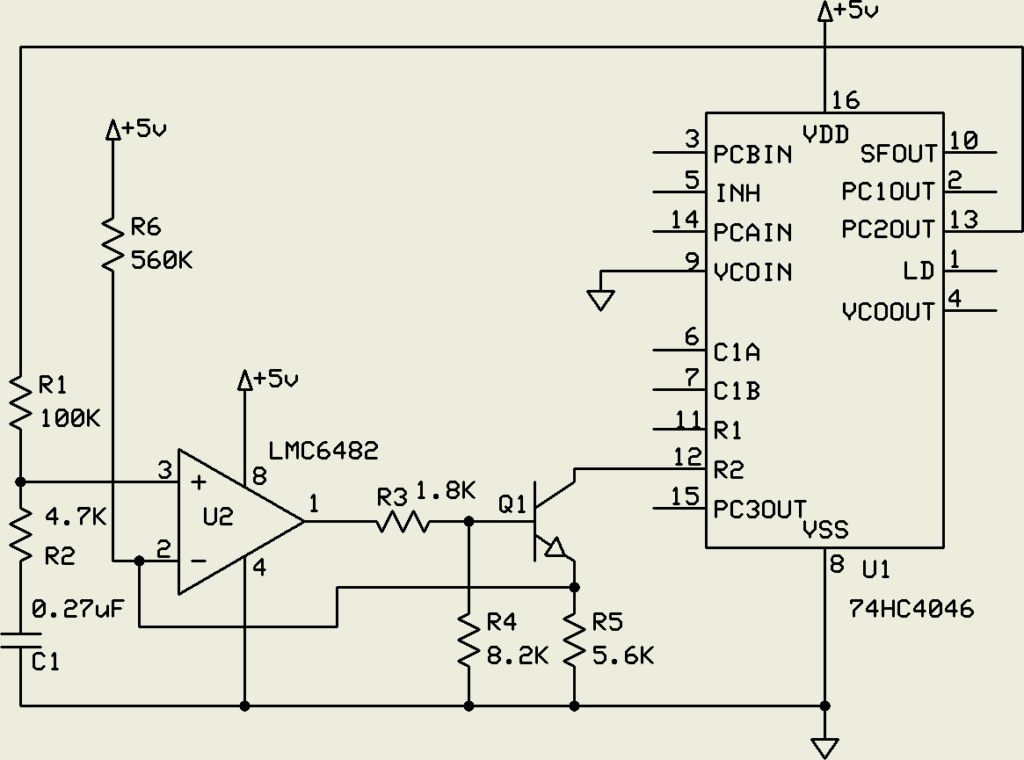
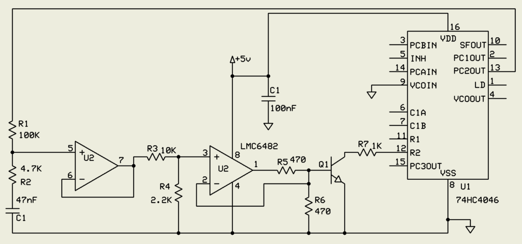
Note that the response at the high frequency end is oscillatory and highly under damped with a settling time of about 200 milliseconds.  The low frequency response is highly over damped with a similar settling time.  The loop filter constants were chosen to equalize settling times.  Improving either degrades the other.  This circuit uses a CD74HC4046 for a faster VCO at 5 volts.  Unlike the CD4046, the HC4046 VCO has a limited common mode range at the VCOin pin and is normally only capable of a  5 to 1 frequency ratio.  To get ratios of 300 to 1 or higher there is a simple workaround.

By grounding the VCOin pin and applying the VCO signal as a sinking current source to the frequency offset input the full range of the VCO is available down to essentially zero Hz.  R6 raises the low frequency voltage enough to avoid Vos problems with U2. R3 and R4 limit the Q1 common mode range to keep it under the pin 12 bias point.

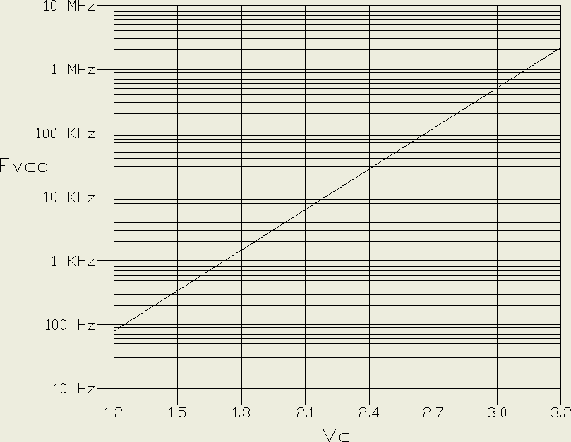
The RCA application note suggests switching in different loop filter components for different frequency ranges but this doesn’t really fix the problem and is less practical with digital control.  Traditional PLL loops have linear VCO gains.  This is essential for applications such as FM modulator / demodulators.   The main insight here is that the settling time is determined by the loop gain at the target voltage.  The gain at other voltages is not relevant.  If, as the division ratio increases, the VCO gain could be increased, the two would cancel and the damping factor would be constant, allowing simple loop compensation.  The solution is an exponential VCO gain response with a low gain at low frequencies (low VCO input voltage) and high gain at high frequencies.

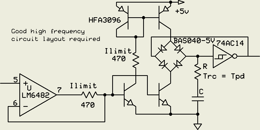
The exponential VCO gain is 4.5KHz per volt at 1KHz and 4.5MHz per volt at 1MHz.  One thousand times higher gain at one thousand times the frequency.  The question arises as to how to make such a VCO.  The obvious solution is to use the Vbe versus Ic relation of silicon junction transistors.

The 470 ohm resistors protect the transistors in case of fault or overload.  The diodes are Schottkys.  R provides a phase lead to the integrator to compensate for the propagation delay of the Schmitt gate at high frequencies.  The matched pair HFA3096 transistors have a gain-bandwidth product of 8GHz which precludes ordinary breadboarding due to parasitic oscillation.  A lower speed design was used for this implementation.

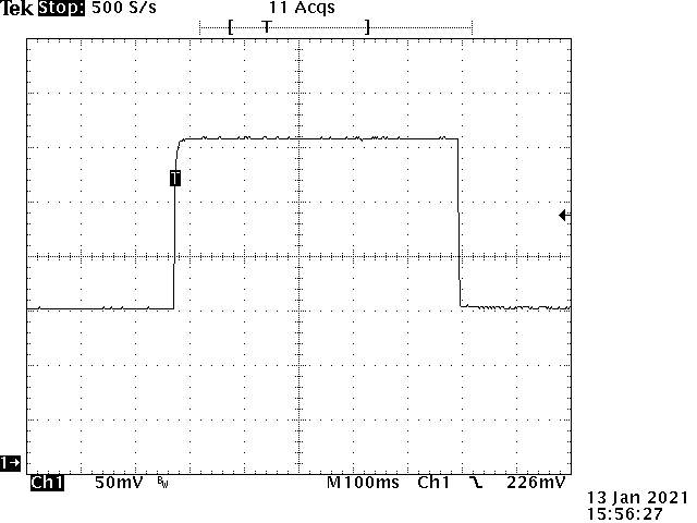
This circuit generated the gain graph above.  Q1 is sufficient for the exponential function.  As this is only needed for loop stabilization the Vbe temperature coefficient is irrelevant.  Note that the loop compensation filter capacitor is one fifth the size of the linear VCO circuit above.  The 3KHz to 1.024MHz step response of this circuit is:

The settling time for both transitions is 900uS and, when zoomed in, both edges are critically damped at high and low frequency.

These kinds of frequency multipliers are useful for synchronous sampling of repetitive signals such as FFT analysis of variable speed rotating equipment at varying resolutions.  While FFTs usually are preceded by a windowing  function to avoid asynchronous artifacts, these functions broaden spectral lines and reduce the spectrum resolution.  With the ability to select FFT sampling rates that are, for instance, 256, 1024, or 4096 times a repetitive signal with a phase locked sampling clock, the requirements for  windowing functions can be reduced or even eliminated.  This enables trading between resolution and data processing overhead for optimized real-time monitoring.

Please leave any comments using the post in my comments category.


An Alternative to Dark Energy

In 1998 when the accelerating expansion of the universe was reported by two groups, the astrophysics community shortly declared the existence of some kind of “dark energy”.  While no one knew what this was, physicists invoked things like Einstein’s Cosmological Constant and vacuum energy to fit it to various theories.  As John von Neumann famously quipped, “With four degrees of freedom I can fit an elephant.”  While there are theories that attribute the acceleration data to local rather than global effects or sampling issues let’s assume the acceleration is real and global.  If so and the acceleration is caused by dark energy / vacuum energy / cosmological constant, the universe may come to a practical end in terms of habitability in 500 billion years or so.  This is a long time and may be an optimistic estimate.

Here’s an alternative to dark energy.   The starting point is the question:  Why are we here — now?   The philosophical name for this is the doomsday argument.  The basic idea is that while the universe is supposed to last for trillions of years fading into a heat death, here we are at the very start, only 13.8 billion years in, only 1% of the first trillion years.  Since the early universe did not generated the elements needed for life, the ratio is even worse.  Being born “now” in the universe seems unlikely.   Locally, even with speed of light limitations, we should be able to spread around our galaxy in no more than a few million years.  We have found out recently that most stars have planets.  Out of the 400 billion star systems in the Milky Way, there are perhaps a billion suitable planets that we could populate.  If that is going to happen, finding ourselves on a single planet out of a possible billion is unlikely.  If you reach into a jar with 10 balls numbered 1 through 10 and pull out number 6, nothing seems odd.  If you reach into a bin with a billion balls, numbered 1 through 1,000,000,000  and pull out number 6, that’s weird.  This is a known problem in statistics with a well defined confidence interval based on how close you are to the start of something.  What it boils down to is that a random sample can be expected to occur between 3 and 97 percent of the range.  If you pull out a 6 the first time you can be 95% confident that there are between 7 and 200 balls total.   After 13.8 billion years we can expect the universe to last from 200 million to 445 billion years from now.  Homo sapiens have been around for 200,000 years, so to be here now, we expect H. sapiens to last another 6 thousand to 6 million years.  The implication is that we may not be around long enough to populate the galaxy and/or the galaxy may not be around as long as we think it will be.  The first possibility involves things like global nuclear/biological war, asteroid strikes, and the like.  The second possibility is the subject of this post.

We are alive at about the earliest time possible in the history of the universe.  Modern scientific discoveries have moved this forward.  The original Milky Way consisted of population 3 stars made up of hydrogen and helium and little else.  Life was not possible.  Some of these stars ended their lives as supernovae creating and ejecting elements like nitrogen, oxygen, calcium, phosphorus, and carbon necessary for life as well as iron and nickel useful for making solid planets.  These enriched the hydrogen clouds that eventually were swept into the formation of population 2 stars, some of which ended as supernovae producing the additional elements that went into the formation of population 1 stars like our sun 4.5 billion years ago which is already 2/3 of the current age of the universe.  So far, so good.  Fifty years ago the assumption was that the solar system was typical and life was inevitable.  The earliest life appeared nearly 4 billion years ago.  It took 3.5 billion more years for anything more advanced than bacteria to appear.  450 million years later we’re here.  Presumably other paths would create self-aware life earlier.

Then modern science complicated the picture.  While we have discovered that most stars have planets, the solar system is atypical and most systems have hot Jupiters and other barriers to the kinds of planets that are needed for life.  In our system, the Jovians, rather than eating the terrestrial planets, protect them by clearing the inner system of asteroids and comets.  Quite unusual and unlikely.

Then there’s the Moon.  The Moon is by far the largest moon compared to the planet it orbits.  It is responsible for tides that may have been necessary to enable the movement of life from the seas to the land.  More importantly it stabilizes the earth’s rotation axis, keeping the seasons regular.  Without it, the earth would slowly tumble, alternating freezing and desert climates, and preventing the emergence of complex life forms.  But the moon is almost impossible dynamically.  As a result of the Apollo sampling missions and modern computer simulations we have a pretty good idea what happened.  At some point a few tens of millions of years after the formation of the solar system a fortuitous Mars sized body slammed into the earth at just the right angle and speed to create a spinning disk of rubble that eventually settled into the earth and the orbiting Moon … an extraordinarily unlikely event.

Uranium is the next issue.  The radioactive uranium in the earth’s interior has kept the iron/nickel core molten for the last 4.5 billion years.  This allows the core and mantle to produce a magnetic field.  This field shields the the earth and the life on it from the solar wind and solar flares.  Without it the earth would be a radiation seared wasteland like Mars and the Moon.  The problem is, where did the uranium come from?  We know it was not part of the early universe.  And it turns out, the supernovae that produce lighter elements are not able to produce uranium.  No uranium, no life.  Enter LIGO, the gravity wave observatory.  Analysis of the gravity waves yields a possibility.  Most of the “visible” events are black hole mergers that yield no material output other than gravity waves.  Similarly black hole / neutron star mergers only produce gravity waves.  A few of these events are mergers of orbiting neutron stars.  These produce an outpouring of large nucleus elements including uranium in addition to gravity waves.  While in the minority, we finally have a source for uranium, sort of.  To have a merger of neutron stars we have to start with two orbiting stars both between 10 and 29 times the size of the sun, no more, no less.  Smaller stars turn into white dwarfs without the density to create uranium in a collision and larger stars turn into black holes that do not release anything.  These two stars have to live out their lives, both supernovae without disrupting the other producing orbiting neutron stars.  These then slowly spiral in and merge and explode.  This takes a long time and is quite rare.  This has to happen near a population 1 star forming region to seed the gas clouds with enough uranium for life friendly planets. This would be relatively nearby and 5-6 billion years ago for us.  LIGO sees these events from all over the universe every few weeks, but since there are about a trillion galaxies in the universe,  there may only have been one in the our entire Milky Way galaxy prior to the formation of the solar system.  This tightens the constraints even more and indicates that we are really living at the earliest time possible , which makes a long future for the universe even more unlikely.

Consensus in the astrophysics community is that our universe is a finite unbounded space, probably a 3-sphere embedded in 4 space, just like our planet is a 2-sphere embedded in 3 space.  A recent astronomical geometrical finding indicated that we are indeed in a 3-sphere.  As you can travel on the earth’s surface in 2 dimensions forever without reaching an edge, you can travel in space in 3 dimensions forever without reaching an edge.  Our 3-sphere universe is probably embedded in a 4-sphere and so on.  This hierarchy sounds like an infinite universe but not really.  As it turns out the volume for an N-sphere of a given radius only increases up to the 5-Sphere and then starts decreasing rapidly and the infinite sum converges.  If you add up the volumes of all the hyper-spheres of unit radius (say one universe radius) the total volume is 45.99932…, ie. the total of volume all the finite universes is finite.  (Yes, it’s turtles all the way down but they get very tiny quickly.)  I’m ignoring the various infinite multiverse theories as these appear to be string theorists grasping at straws.  A 1-sphere on a 2- sphere is a circle like a fairy ring of mushrooms on the surface of the Earth.  The ring has a finite interior that takes up a finite fraction of the surface of the earth’s 2-sphere surface.  The ring has a center which is part of the 2-sphere but not on the ring.  Earth’s surface 2-sphere has a finite volume that takes up a finite fraction of the 3-sphere we live in.  It has a center that is in the 3-sphere but not on the surface.  Similarly, our 3-sphere 3 dimensional universe has a finite volume that tales up a finite fraction of the 4-sphere it’s embedded in.  It has a center in the 4-sphere that is not in the 3 dimensional 3-sphere universe.  That center probably shares 4 dimensional coordinates with the center of mass of our universe and the historic location of the big bang in four space.  Our expanding 3 sphere universe spreads through the 4-sphere just like a fairy ring spreads over the surface of the earth.  The main point here is that if the total multidimensional universe is eternal and “big bangs” happen on a regular basis, the finite 4-sphere will have already filled up with expanding 3-sphere universes which, if they persist, will be banging into each other.

As scientists were searching (successfully) for the hypothesized Higgs Boson, vacuum decay entered the discussion.   This represents the possibility of a point quantum event that disassembles and destroys everything the the universe, with the wave front traveling at the speed of light.  While this is considered unlikely, the science is  not settled.  There is also the possibility that a collision of 3-spheres could trigger such an event.  We may live in a soap bubble waiting to be popped.  Since most of the universe is beyond our light speed horizon it is possible for such an event to occur without ever reaching us through three space.  It is conceivable that shock waves propagating through 4 space are faster than the 3 space speed of light, much like seismic P waves propagating through the earth faster than the surface S waves.  While the decay event propagates through the 3-sphere, the shock wave could couple to 4 space and travel across the 3-sphere interior much faster.

Perhaps 5 billion years ago a decay event occurred somewhere in our universe.  The initial decay volume produced a pressure shock that propagated in 4 space across the 3-sphere internal volume and inflated the universe slightly.  As the surface of the volume of destruction increased, the generated shock increased which increased the inflation of the rest of the 3-sphere.  Thus the existing expansion of the universe appears to accelerate.  If this event occurred within our horizon, that may explain why we aren’t here much later.

On a happier note, assume the bubble doesn’t ever pop.  Two popular scenarios in that case are the Big Rip and Heat Death of the Universe.  Both involve runaway expansion leading to an effectively empty, infinite universe.  Really boring.  Consider the fairy ring — when it’s a few feet in diameter we can imagine it expanding forever — but we know that if it did, it would crunch back together on the other side of the earth (ignoring oceans and deserts).  Similarly any Big Rip or Heat Death will eventually meet itself on the other side of the 4-sphere.  Who knows, it may start another big bang.

Please leave any comments using the post in my comments category.
Semaphores

Multiprocessor or multitasking systems need a mechanism to coordinate inter-processor or inter-task communication.  In shared memory architectures the lowest level parts of this mechanism are usually called semaphores.  These can be used to request a resource such as I/O.  Typically this is a memory location that is tested to see if the resource is free and then set to lock out other actors.  Unfortunately an interrupt or separate processor might intervene between the test and set.  Some, but not all, processors have implemented test-and-set instructions that cannot be interrupted.  This protects against other tasks but the test-and-set instruction must also work with dual port memory and cache systems to hold off other processors.  The main problem is allowing multiple actors simultaneous write access to the same memory location.  Various solutions have been tried.  Some years ago, the UNOS operating system developed by Charles River Data Systems implemented eventcounts for low level signaling.  These 32 bit objects could only be incremented, preventing some of the problems with test-and-set semaphores.

For real-time industrial control a much more robust solution is necessary that satisfies a set of requirements.  1. Semaphores must be deterministic without the possibility of race conditions or ambiguity.  2. The solution must not require special processor features to allow portability.  3. Each semaphore is an entire smallest memory object that is written with a single memory cycle, usually an 8 bit byte or alternately 16 bit word for pure 16 bit memories.  4. Semaphores are provided in Query (Q) / Response (R) pairs. 5. Only one client actor may write a Q semaphore and only a single different server actor may write the associated R semaphore.  6. Each resource, be it a memory buffer, I/O, master state machine, or other is under the control of a single actor.  7. Enough distinct Q/R pairs are allocated to each client/server channel to unambiguously control all transactions.  8. At system configuration, and later as needed, semaphore pairs are assigned to client/server channels to establish the required communication channels.  9. Different processors or tasks may be servers for different resources.  10. Query and Response actions are performed in a single memory cycle.

As an example, when a channel is inactive, Qa and Ra are equal.  The specific value is irrelevant.  The client compares Qa and Ra.  If they are equal, the client may place a Query to request access to a resource such as a shared memory buffer by writing the logical complement of Ra into Qa.  When the resource becomes available the server copies Qa into Ra which signals the client that the buffer is available for reading and writing.  When the client finishes its data/control access it sends a query to Qb by writing the complement of Rb to it.  This signals the server that the client is finished with the buffer.  The server copies the Qb to the respective Rb to signal that it has regained control of the resource.  Note that this last is useful as otherwise the client might think the buffer is already requestable since Qa = Ra.  Bidirectional control transmissions may be passed from the server back to the client using additional Qc/Rc, Qn/Rn, … semaphores where Q is the server side.

Alternately, the above transaction could be

Client: [Qa = not Ra] ->

Server: [Qc = not Rc] ->

Client: Access …  -> [Rc = Qc] ->

Server: [Ra = Qa]

Note that in either case, the source of the query always sets the semaphore pair to a different value and the responder to the query always sets the semaphore pair to the same value.  In other words, an actor is not allowed to change its mind.  An abort request must be handled by a separate Q/R pair.  This is absolutely necessary for deterministic behavior.

This strategy works well in main memory for separate tasks and threads, shared memory for multiprocessors, and in hardware for handshaking to control communication buffers.

Please leave any comments using the post in my comments category.
Knurling on a Small Lathe

First a short note on lathe safety.  Modern industrial CNC lathes and machining centers have comprehensive safety systems including guards and light curtains.  Hobby and bench lathes are a completely different animal.  While a table saw or band saw will take off fingers, carelessness with a lathe will kill you.  Do not wear long sleeves or jewelry to include rings, bracelets, wristwatches, or necklaces.  Do not wear gloves.  Do not wear a tie, Bolo, or scarf.  Tie your hair back if it’s long.  Do not wrap crocus or emery cloth around your fingers to polish a moving part.  If you’ve had a drink, put off the lathe work until tomorrow.  Operating a lathe requires continuous attention, concentration, and clear judgement.  If you are interrupted or distracted, disengage the feed and step away from the lathe before turning to address the issue.

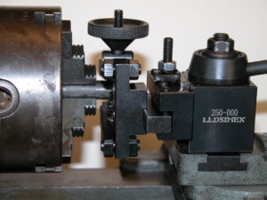
Knurling on a lathe is usually performed with a push type toothed roller tool as shown in figure 1.  The tool is pushed into the rotating part using the cross-slide.  This works fairly well on 12 – 14 inch and larger lathes.  Scaled down versions are traditionally supplied with smaller 6 and 7 inch lathes.  Figure 1 illustrates the tool supplied with the 6 inch Atlas lathe.  Using Atlas as an example, the 6 inch lathe looks just like the 12 inch, only scaled down.  The problem here is that a 6 inch lathe is not adequate to press regular knurls into harder materials like steel or brass.  The lantern tool holder and the cross-slide are simply not strong enough.  While it looks like it ought to work,  for proportional cross sections, a 12 inch lathe is 8 times stiffer and stronger in bending and 16 times stiffer and stronger in twisting than a 6 inch.  On YouTube, mrpete222 (tubalcain) has videos (#333-#336 ) about making a new 6 inch Atlas cross-slide to replace a broken one that obviously had too much force applied to the tool post.  I speak as someone who has broken a 6 inch Atlas/Craftsman lantern, although not while knurling.  The one in figure 1 is a slightly beefed up O1 replacement tempered to RC50.

Figure 1

Another problem with push type knurlers is that the stock has to be strong enough to resist bending under the knurling force and may need to be supported with a live center or steady rest.

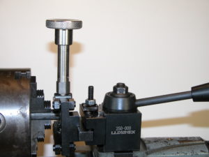
A solution to both problems is the pinch style knurler shown in figure 2.  In this style the part is trapped between an upper and lower roller.  Depending upon the model, the diameter is adjustable from 1 or 2 inches down to zero.  Since all the knurl force is due to the pinch between rollers there are no unbalanced forces against the work piece or the tool holder.  This allows knurls on unsupported long parts without difficulty.  The cross-slide simply centers the knurl wheels on the part and the carriage travel is used to make longer knurls.   As a result deep knurls on steel are easily produced even on the smallest lathes.  The remaining difficulty is that to start the knurl, the work piece needs to be turning while the clamping knob is tightened to the desired depth.   On short parts to be knurled near the chuck the small clearance between the spinning chuck and the hand adjust knob creates a major safety problem.  Figure 2 shows a stock tool.

Figure 2

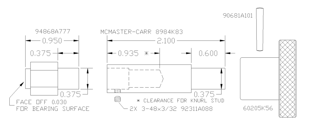
Here is the solution I came up with for my lathe.  A 3 inch extension of the clamp knob moves my hand far enough from the chuck for comfort.  I am not suggesting that you do this, just reporting on my solution to a perceived hazard.

Figure 3

I used a through tapped spacer from McMaster-Carr for the thread as I didn’t have a deep hole M6 tap and didn’t feel like counter boring all the way from the top.

This is pretty mundane but now there’s one less thing for me to worry about.  By the way, the 0XA quick change tool holder as shown works well on the Atlas 6 inch.  Cutoffs are WAY better.  You will need to cut rabbets on the plate that comes with the tool holder as can be seen in figure 2.  A single piece of steel the thickness of the T-slot is not strong enough for a solid tool holder lock-down.  It flexes and doesn’t have enough thread engagement.

Please leave comments using the post in my comments category.
Staying alive on Venus

The most hostile place in the entire solar system that it is possible to land on is the surface of Venus.  The airless sun-baked surface of the Moon only gets to 260°F during daylight.  The surface of Mercury, closest to the Sun, peaks at 801°F.  But the surface of Venus is at 872°F both day and night with a corrosive atmospheric at a pressure of 1350 psi or 93 times the Earth’s.  The Russians, famed for rugged equipment, have landed probes on Venus at least 11 times.  The record for lander survival was set by Venera 13 on March 1, 1982, at 2 hours and 7 minutes.  Venus survival is so difficult that NASA is soliciting outside ideas with their Venus Rover Design Competition.  They are looking for ways to control and maneuver rovers without computers or electronics.  The main problem is that modern electronic devices cannot stand this kind of heat and die completely at 400°F or so.  It is completely infeasible to try to refrigerate the sensitive electronics and sensors because of the power requirements and the very high thermal gradient any refrigeration system would have to fight through. Not just the semiconductors and processors, but even current insulation and substrates, will not work at anywhere near these temperatures.  Nor will ordinary power sources.  Any lander will be accompanied by one or more orbiters that can receive information if it can be gathered.  Some creative ideas involve radar reflective panels that can be moved mechanically to change the lander albedo to signal data to an orbiter.  Others involve purely mechanical means for using extended probes to steer around holes and obstacles.

If you assume a pressure vessel, so the internal parts of the lander can be maintained at low or zero pressure to eliminate corrosion issues, the remaining problem is temperature.  While 872°F exceeds the working temperature of most engineering technology, this environment is actually within the reach of the amateur.  A typical self-cleaning kitchen oven runs at 900°F for a 4+ hour cycle.  Not as fancy as NASA’s Venus Surface Simulator but useful for testing magnets, bearings, insulators, and mechanisms.  One proposed solution to the power source problem is a windmill.  While the average wind speed on Venus is only 3 MPH, the air density is 93 times higher than on Earth, providing plenty of power for a windmill.  The main problems are bearings and power transfer.  There are hybrid ceramic and carbon sleeve bearings which are rated for these temperatures although not these pressures in this atmosphere.  Magnetic bearings eliminate friction and corrosion issues.  Unfortunately, the current top magnet material, Neodymium-Iron-Boron, loses its magnetism at such temperatures.  The next best, Samarium-Cobalt, has some high temperature versions that will only lose part of their strength.  These can be preconditioned at temperature and then used.  The older ALNICO 9 is able to work at Venus temperatures but starts out with about 1/3 the strength of Samarium-Cobalt.  It’s not clear which of an ALNICO or SmCo solution would be lighter and/or smaller.  Power could be transferred into the pressure vessel through a magnetic coupler consisting of a permanent magnet rotor surrounding an internal stator/generator separated by a nonmagnetic stainless steel cup in the wall of the pressure vessel. The overall idea is to figure out how to accomplish the science goals with technology that can operate at 872°F.

While NASA is looking into silicon carbide semiconductors, there are other possibilities.  One possibility is old tech: vacuum tubes.  In 1959 RCA invented the nuvistor, an advanced 0.4”x0.8” subminiature metal/ceramic vacuum tube.  While the kinds of glass subminiature tubes used in the AN/PRC-6 “walkie-talkie” radio might work at these temperatures, the nuvistor technology would be a better starting point.  One interesting feature was the RCA “dark cathode” that operated 630 degrees cooler than standard filaments.  The reduced heater operating temperature resulted in greatly increased tube life and reliability.  Starting at Venus temperatures would significantly reduce filament power.  More advanced materials might allow a Venus ambient temperature cathode without heater power.  The main problem is thermionic emission leakage from the grid, which limited the maximum temperature for the nuvistor.  In an advanced design, vacuum depositing a silicon dioxide film on the grid might produce an analog of an insulated gate, suppressing grid leakage.  There are metal-ceramic transmitter tubes like the 4CX150 that could be used as a starting point for developing high-temperature transmitter finals.  Circuit connections would need to be welded rather than soldered.  Most components would need to be rethought since traditional insulators will not work.  Capacitors could be air, glass, mica, or suitable ceramics.  Resistors could be metal film on ceramic or wire-wound on ceramic cores.  Inductors would be printed on ceramic laminated substrates or air-wound on ceramic spacers.  This is mostly existing radio technology.

One application would be small instrument packages that could be dropped in large numbers, consisting of a few simple sensors, a vacuum tube transmitter, and a solid electrolyte battery.  These are batteries already in use by the military.  They are extremely rugged and are completely solid and inactive at room temperature.  They are intended to run at temperatures in the Venus range where the electrolyte melts and becomes active.  Normally these batteries are actuated by pyrotechnic charges in artillery shells, rockets, or such but they could be part of a constellation of small Venus probes reporting temperature, seismic activity, or other data over wide areas for a limited time.  They would easily survive a multi-year space flight prior to insertion.  Multiple waves of probes could be used for longer data sets.

A long-term lander with a wind power source could support a wider range of sensors over a longer time frame.  With a method to generate high enough voltages and development of a high temperature photo cathode, it should be possible to use an image or line orthicon to transmit spectra.  Sapphire, ALON, or quartz windows would allow light sensing and slow-scan imaging.  Decades of television before the 1960’s demonstrated that this is well within the range of tube technology.  Mechanical scanning from an even earlier era is another possibility.  With magnetic bearings in a vacuum environment the scanner power consumption could be very low.  An idea brought up by various people is that you don’t need a computer or controller on the surface; you just need a receiver and transmitter in the lander with a control computer in the orbiter or orbiters.  Kind of like a really expensive drone.

Although NASA is looking into making processor chips out of silicon carbide, a non-trivial task, for over a decade computers were designed with vacuum tubes.  All logic functions, nand, nor, register, etc, can be handled by tubes, which in modern guise could be very small and very low powered compared to the best of the tube era, the nuvistor. While the original tube computers were monsters, they needed to run fast to solve major problems in a reasonable amount of time.  You don’t need much of a computer to miss a rock or transmit some data.  Specifically, a one-bit architecture like the PDP-8/S, WANG 500, or Motorola MC14500B with a little memory can compute anything with a minimum of physical hardware.  While it would be slow, it would minimize size and power consumption while providing adequate control for the lander.  A high temperature version of the Mercury computer program store could be a possibility here.

Please leave comments using the post in my comments category.

A23 Panel Mount Battery Holder

If you decide to use an A23 battery (small cylindrical 12V) in a project you will discover that there are no A23 panel mount holders available.  If you don’t want to open your enclosure to change batteries, here’s a suggestion.  The A23 fits in a Bussmann HPF fuse holder but is slightly too short.  You can use a 3/8″ (or 100 mm) diameter brass disk,  0.280″ (or 7.1mm) long, dropped into the panel side of the holder to extend the back contact.    Insert the negative end of the battery into the cap where it is held by friction and screw in the cap with the battery positive end against the brass spacer.  The internal spring will compress about 0.035″ as the cap is screwed in to maintain battery contact.  The Bussmann terminal labeled “LINE” will then be the +12 terminal.

Bussmann makes variants of the HPF holder for non-standard fuses that still require a (shorter) brass spacer but the plain HPF is the most common and easiest to find.  allfuses.com had by far the best price for these I could locate.

Please leave comments using the post in my comments category.

Reinstalling screws into plastic

We live in a world of plastic consumer goods held together with screws.  These are thread-forming screws with sharp threads that cut threads into unthreaded holes in the molded plastic parts with the intention of never being removed.  Unfortunately sometimes removal is necessary for repair or, increasingly, simply to replace batteries in inexpensive goods.  The problem is that simply screwing the fasteners back in cuts new threads each time, destroying the integrity of the plastic threads and the strength of the joint.  All is not lost, however:

There is a technique to reinstall thread-forming screws without damage.  Place the screw at the start of the hole on the end of your screwdriver.  Using the tips of your fingers loosely on the shaft of the screwdriver, turn it backwards, i.e. counterclockwise, with only the weight of the screwdriver pushing on the screw.  Since the screw is turning backwards the sharp threads will not cut into the plastic.  Turn until you feel or hear a light click – immediately stop.  This means that the screw thread has dropped into the start of the original plastic thread channel.  Now turn the shaft gently forwards, clockwise, to make sure the screw threads slide in smoothly.  If so,  run the screw in.  Do not over torque it.  When you feel it bottom out, stop turning.  That will be firm enough for most plastic assemblies.  If it does not turn easily or feel smooth,  back off and turn backwards feeling for the click and try again.  Some screws are called double lead or hi-lo and have two thread heights.  In that case you will get two clicks, one lighter and one harder.  The harder click is the proper thread channel.  In general it is a good idea to turn backwards at least a full to turn to find the most definite click.  This can also make the best of an already compromised hole.

This technique works as well for reinstalling wood screws without damaging the threads in the wood.  It also works well to avoid cross threading things like wide-mouth cosmetic jars and threaded photographic filters, especially ones made from aluminum.

While I’ve done this for decades, I was reminded that it is not a universally known technique while working on my Dyson vacuum.  These are pricey vacuums with the subassemblies held together internally with screws that you really want to be careful with.  The subassemblies themselves snap to each other.  Dyson only sells subassemblies on their web site that can be replaced without removing and replacing screws.   As all I needed were beater bars and not the entire floor head I kept looking.  I found the smaller parts I needed at evacuum.com for much less than the assembly cost.  After carefully removing the old parts and installing the new screwed on parts without damage I realized why Dyson only sold snap-on parts to consumers but sold smaller parts to dealers.  They did not want consumers to inadvertently  damage their units trying to repair them, but assumed repair shops would know how to do this safely.

Hence this post.  I hope it helps you with future plastic and wood repairs.

Please leave comments using the post in my comments category.